GPIO shared with LED Col 9 of the LED screen can be used for digital I/O when the LED screen is turned off. When the button is pressed, the voltage on pin 5 is pulled down to 0, which generates a button click event. To replace button A on the micro:bit with an external button, connect one end of the external button to pin 5 and the other end to GND.

This pin has a pull-up resistor, which means that by default it is at voltage of 3V. This lets you trigger or detect a button “A” click externally. GPIO shared with LED Col 2 of the LED screen can be used for ADC and digital I/O when the LED screen is turned off. GPIO shared with LED Col 1 of the LED screen can be used for ADC and digital I/O when the LED screen is turned off. The following pin tables describe the pin functions for each version. There are some differences in function assignments for the small pins between the micro:bit versions. For example, pin 3 is shared with some of the LEDs on the screen of the micro:bit, so if you are using the screen to scroll messages, you can’t use this pin as well. Unlike the three large pins that are dedicated to being used for external connections, some of the small pins are shared with other components on the micro:bit board. The 20 small pins are numbered sequentially from 3-22 (these pins are not labeled on the micro:bit, however, they are labelled in the picture above). If you hold the GND pin with one hand, you can program the microbit to detect yourself touching the 0, 1 or 2 pins with your other hand, giving you three more buttons to experiment with (you just used your body to complete an electrical circuit to make “resistive touch” buttons). GND: attaches to ground in order to complete a circuit (required when using the 3V pin).power input: If the micro:bit is NOT being powered by USB or battery, you can use the 3V pin to supply power input to the micro:bit.power output: If the micro:bit is powered by USB or a battery, then you can use the 3V pin as a power output to power peripherals with.3V: 3 volt power output or power input:.Watch out! The pins labelled 3V and GND relate to the power supply of the board, and they should NEVER be connected together.įor details on the power, current and voltage limitations of the board, see Power Supply. The other two large pins ( 3V and GND) are very different! With the micro:bit V2, pins 0, 1, 2, and the LOGO can also be set to work as capacitive touch buttons. 0: GPIO (general purpose digital input and output) with analog-to-digital convertor (ADC).These three pins also have the ability to read analog voltages using something called an analog-to-digital converter (ADC). The first three, labelled 0, 1 and 2 are flexible and can be used for many different things - which means they are often called “general purpose input and output” (shortened to GPIO). You can easily attach crocodile clips or 4mm banana plugs to the 5 large pins. And along the same edge, there are 20 small pins that you can use when plugging the micro:bit into an edge connector. There are 5 large pins that are also connected to holes in the board labelled: 0, 1, 2, 3V, and GND. The edge connector is the gold area on the right side of board as shown the figure below. My suggestion - in the case of pattern unlock, do not allow "Use Visible Pattern" or "Use tactile feedback" under Settings > Location & security settings, to minimize breach.īut however, your question is a worthy +1 from me from a security viewpoint.The micro:bit has 25 external connections on the edge connector of the board, which are referred to as ‘pins’.

Despite saying that, one could theoretically sprinkle a bit of powder on the screen and gently brush it away to see where the fingerprint is on but that's going OTT on the other hand, that is, if you watch too much NCIS. The other thing I can think of is to use a screen protector, in that way, the smudges will show on it but not on the actual touchscreen. Almost bordering on using malware techniques to achieve it.
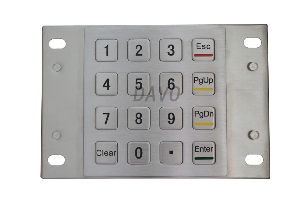
#Pin keypad layout android
The lock-screen's pin mechanism is in-built and to override that mechanism requires going down the unofficial programming interface that does not have the approval from Google's Android development aspect. I would not be surprised if there's a soft keyboard layout that appears at random intervals but I suspect its never thought of as it would drive users batty especially when texting. now you may get funny looks from others, akin to taking off the glasses each time and wiping it cleanly to "see" again if you get my drift. You've pointed out the weakness in the security - smudges on the touchscreen the only thing that I can think of is this - wipe down the screen each time.

I am not sure if this can be done, to scramble the keypad's number layout every-time on unlock to force you to slow down.


 0 kommentar(er)
